Unfortunately, I didn't take any pictures specifically regarding the electrical system before I began to dismantle it. There was a tangle of wiring from the battery terminals leading to the electrical panel. Another tangle of wiring went from the electrical panel and spread throughout the boat.
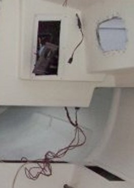
Here is a photo of the tangled wiring leading from the battery terminals to the electrical panel. You can also see the power supply for the VHF radio at the upper right, although this was wired directly from the battery, and not switched at the panel.

Much of the wiring is embedded in the cabin top bonding matrix and therefore cannot be removed nor easily replaced, but several aspects of the existing wiring concerned me. Although considered adequate at the time of construction, the original wiring is below current ABYC standards in wire size, and because it has an incorrect color scheme, since yellow has replaced black for DC negative. It is also less than optimum because it is not tinned, and because it is not jacketed.
All 4 existing circuits were for lighting. I decided to reuse most of the original wiring, but lighten the electrical load on it by switching all lighting to LED. I also decided to add 5 upgraded circuits to the electrical panel, excluding an automatic bilge pump which I am also adding to the system. It will be controlled through a separate circuit.
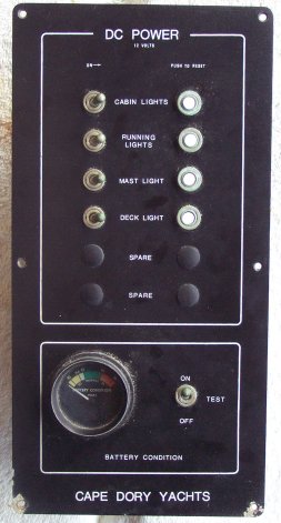
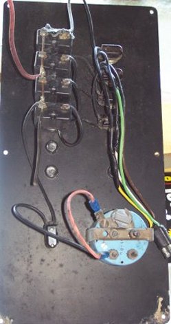
Another curious discovery was that all of the original circuit breakers were 20 amp. This provides marginal safety for the wire gauge it protected. Here are photos of the original DC Electrical Panel, front and back.

