Browsing through the Cape Dory Message Board , I found a reference to Pacer Marine of Sarasota, Florida. Luckily for me, they have an outlet in Fort Lauderdale, about 15 miles from my home. Their wire prices are about a third of West Marine, with the caveat that some (but not all) of their items are bulk purchase only. For me this worked out well, because I saved a lot of money and also had some materials left in reserve.
The time to run new wiring was after stripping the boat. For the 9 circuits I needed, I ran 7 new circuits, which added 5 circuits and replaced 2 of the 4 old circuits. For this upgrade, I used BC-5WC rated red/yellow duplex cable. Two circuits are 10 AWG, four are 14 AWG, and one is 16 AWG.
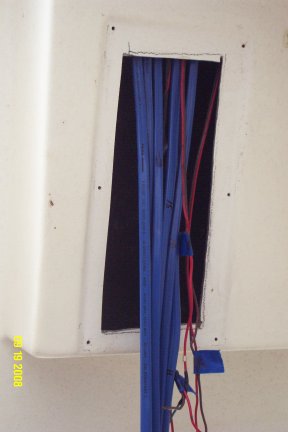
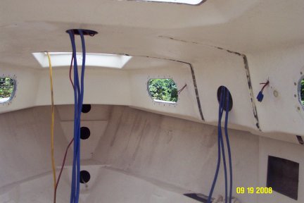
Here are photos some of the new wiring I have installed, and some of the original wiring. The first photo shows the electrical box where the panel will be mounted, and the second photo shows the cabin, where wiring is supplied to the mast (center) and the starboard side.
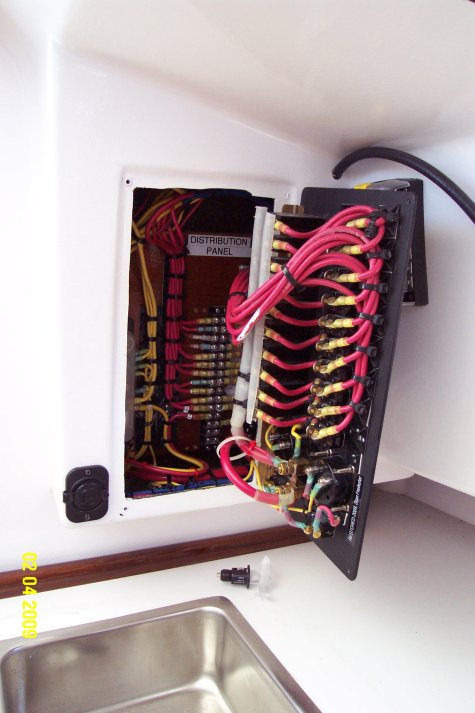
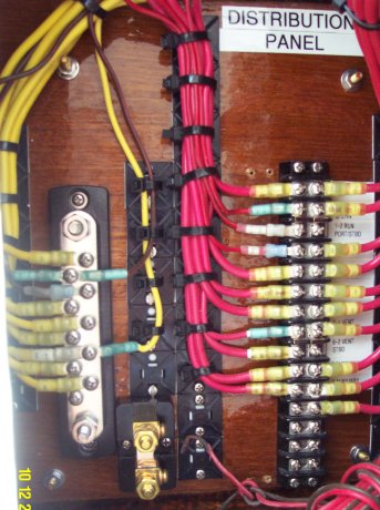
I then began building a Distribution Panel to mount inside the electrical box. This would organize the wiring from the Electrical Panel, the power supply, and the boat's circuits. All wires are catalogued and numbered.
All 4 of the original circuits were for lighting, and were molded into the cabin top matrix so they could not be realistically removed or replaced. I replaced those I could, and decided to lighten the electrical load on the remaining 2 original circuits by switching from incandescent to LED lighting.
I built the DC Electrical Control Panel with a total of 10 circuits (one spare),
a Voltmeter, and an Ammeter. I hinged the panel to make the wiring more easily
accessible.
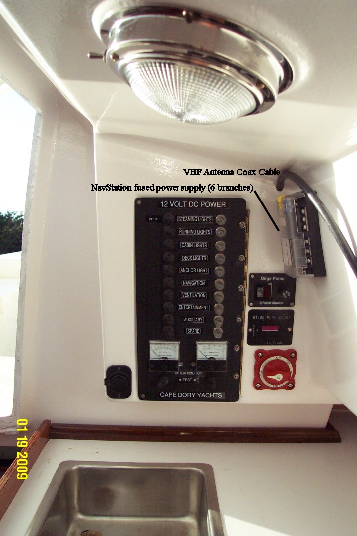
This photo shows the juxtaposition of the Electrical Panel and the Distribution Panel within the electrical box. Above the Electrical Panel, you see the
coaxial cable for the VHF radio. Behind the Electrical Panel is the Navigation Sub-Panel (actually a fuse block) which allows me to fuse up to 6 individual
components of the Navigation Circuit, such as VHF, GPS, AutoPilot, Depth Finder, etc.